LEGO Lift: The Hardware Side
We used the lego component to construct a simple
4-floor elevator with an automatic-door cabin. Calling is done by the
software (because we only had 3 sensor plugs).
The elevator is made of these two components:
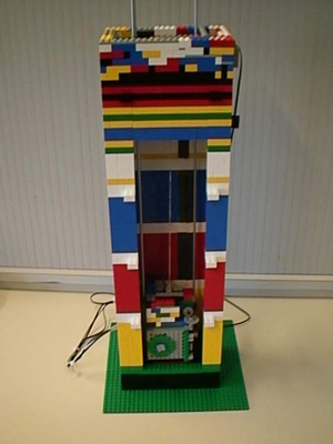
I- The Tower:
Dimensions:
- height: 63.5 lego bricks (about 50 cm)
- width: 22x14 lego pins (about 17.5x11 cm)
 The
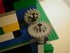
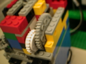
tower includes the motor that lifts the cabin, The
tower includes the motor that lifts the cabin,
which is placed on the upper right side of the tower,
and uses a reducer to get more power to rotate the central axis
on which the pulley is mounted.
 The
cabin is then guided by 3 rails (simple metal tubes) The
cabin is then guided by 3 rails (simple metal tubes)
that are fixed on the top and bottom of the tower.
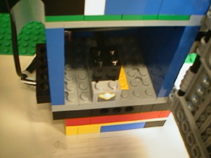
 One
of the big problems encountered was to know at which floor the cabin
was , One
of the big problems encountered was to know at which floor the cabin
was ,
that's why all of them are marked by 2 white rows of lego pieces,
and the interfloor is covered with black paper, so the floor
is detected by a transition between black and white.
Of course you must always start the program at the
same floor and increment a counter to know
the actual floor.
II- The Cabin:
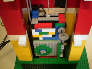
Dimension:
- height:17.5 lego bricks (15 cm)
- width:9x9 lego pins (7x7 cm)
The cabin was the most difficult part of the elevator, 3 main
problems appear in building a complete cabin:
- How will the door movement be detected?
 First
we thought of using the rotation sensor and stopping the door at some
particular values, First
we thought of using the rotation sensor and stopping the door at some
particular values,
but due to answer delay from the computer the door would go too far.
We also noticed that the sensor wasn't always sending the same angle
value for the same position,
so the door never opened the same way each time.
 Then
we decided to put two touch sensor linked to the same entry on the tower,
so when the sensor value was at 1, Then
we decided to put two touch sensor linked to the same entry on the tower,
so when the sensor value was at 1,
the door was either open or closed, this can then be controlled in the
program by a simple state engine.
 But
then we were facing a new problem: when the door was blocking on one
of the interruptors, But
then we were facing a new problem: when the door was blocking on one
of the interruptors,
it jumped and so the state engine was going through false states :
the program wasn't really sure of the door position, and the elevator
had a strange behavior.
To get rid of this we just added a brake in the
door motor reductor (that is at the back of the cabin)
and so when the door was forcing on one of the extremities of its trajectory,
it did not jump but the brake just let the motor rotate freely.
- How would we detect at what floor the cabin was?
First (there is always a first, bad idea :) ) we thought of
using a touch sensor and put some little lego pieces in the tower in
order to code the floor, but there wasn't enough space for that, and
we put this idea away...
 Noticing
that we got a light sensor, we managed to detect each floor with some
light variation. Noticing
that we got a light sensor, we managed to detect each floor with some
light variation.
To do so, as explained in the tower part, we placed
some white lego elements at each floor
and hid with a black band (printed paper) the transition between them.
Since the lego light sensor is quite sensitive,
detecting a transition between
black and white is the simplest way we found to
detect when the cabin passed a floor.
- Only two long cables were delivered with the mindterm package
As we got 3 electronic components (2 sensors and 1 motor) in the
cabin to plug on the rcx tower, we needed one more long cable. We tried
to open a connector of one of the small cables and extend it from there,
but this wasn't possible, so we just cut the cable and soldered a long
cable between the two extremities, and it was done!
|