2.1 Nodes and Application Tasks, Network
The basic concept for implementing the system is that of a distributed system
- where application tasks (for instance: handling the interface to some piece of hardware, generating timed events, allowing the user to interact with the system) are delegated to sub-systems,
- and where these sub-systems are realized as nodes that communicate over a network - the CAN bus.
2.1.1 Types of Nodes
The system supports four types of nodes:
"Target nodes"
The "Master Node" (only one master node may exist on the system).
"Button Nodes"
provide push-button control over a set of devices (controlled by the target-nodes) and - optionally - operate LEDs that indicate the state of the devices. As an example, Figure 2.1.1-1 shows a button board with 10 LED-buttons for mounting in a double-68 mm wall fitting.
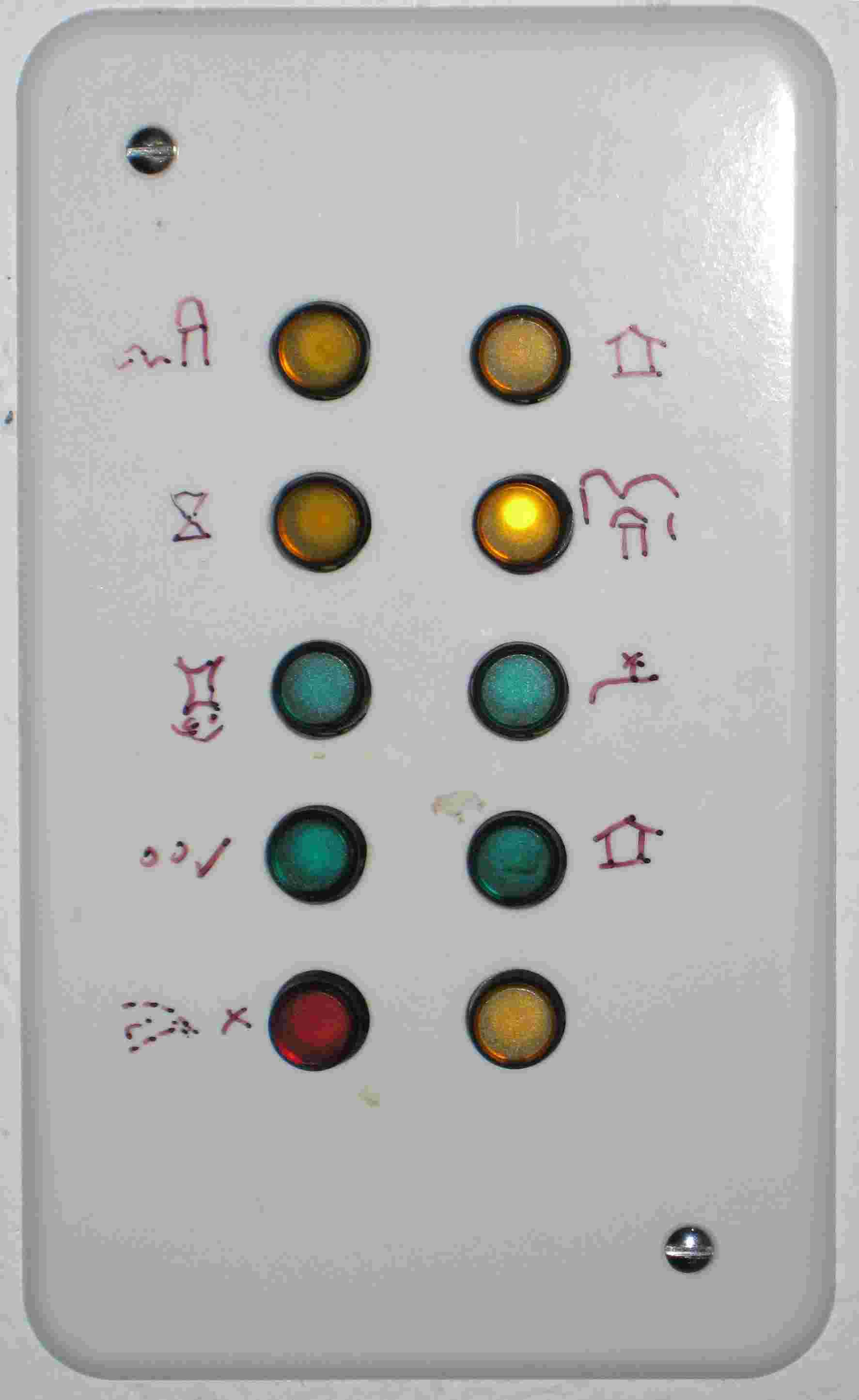
Figure 2.1.1-1: Example of a button-node
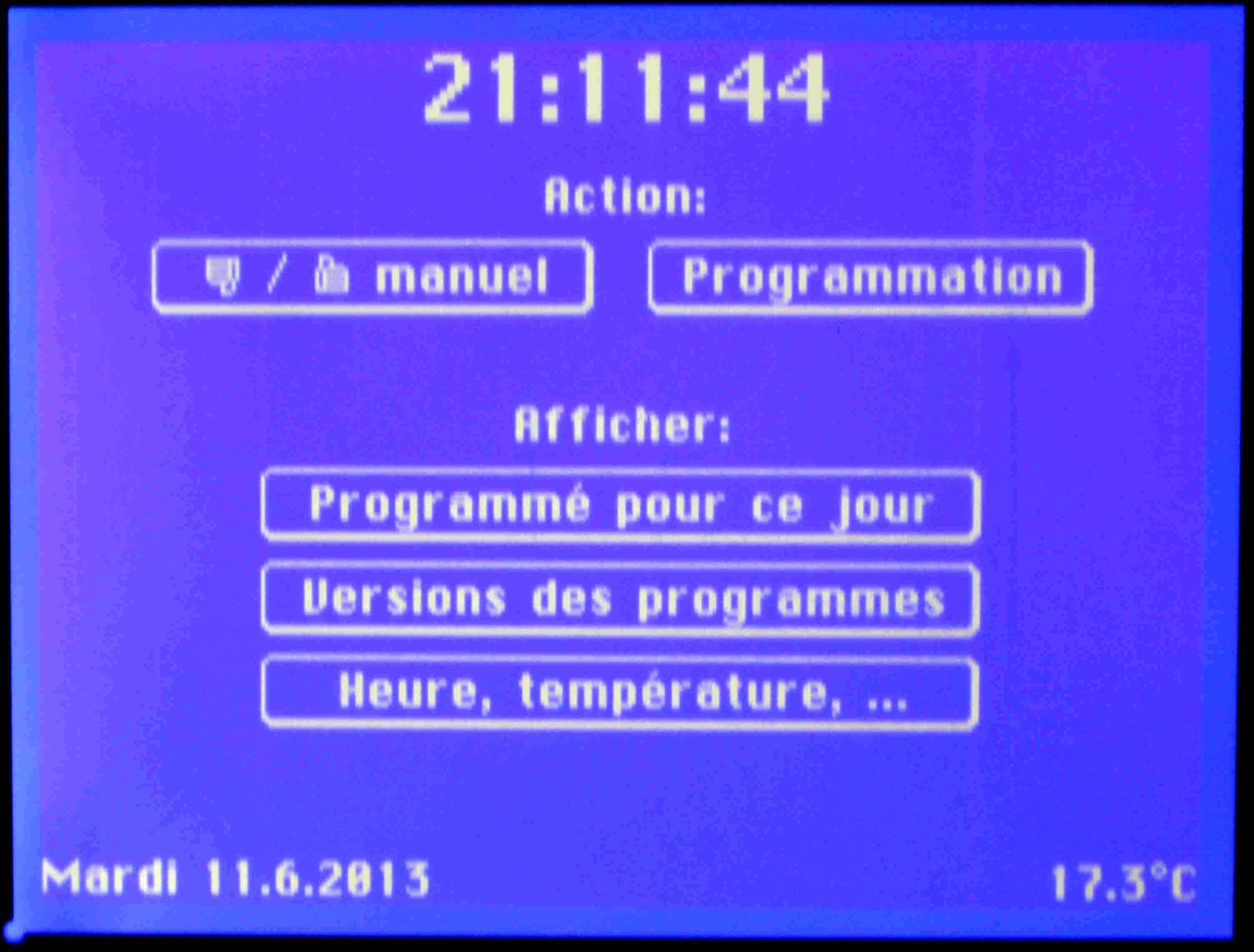
"Display Nodes"
- switching devices on and off,
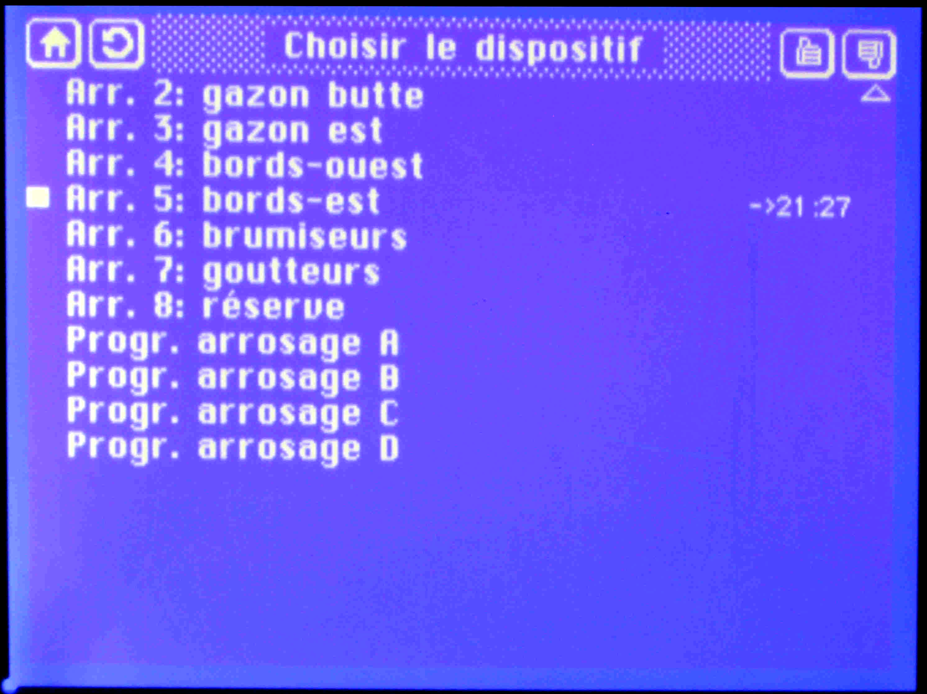
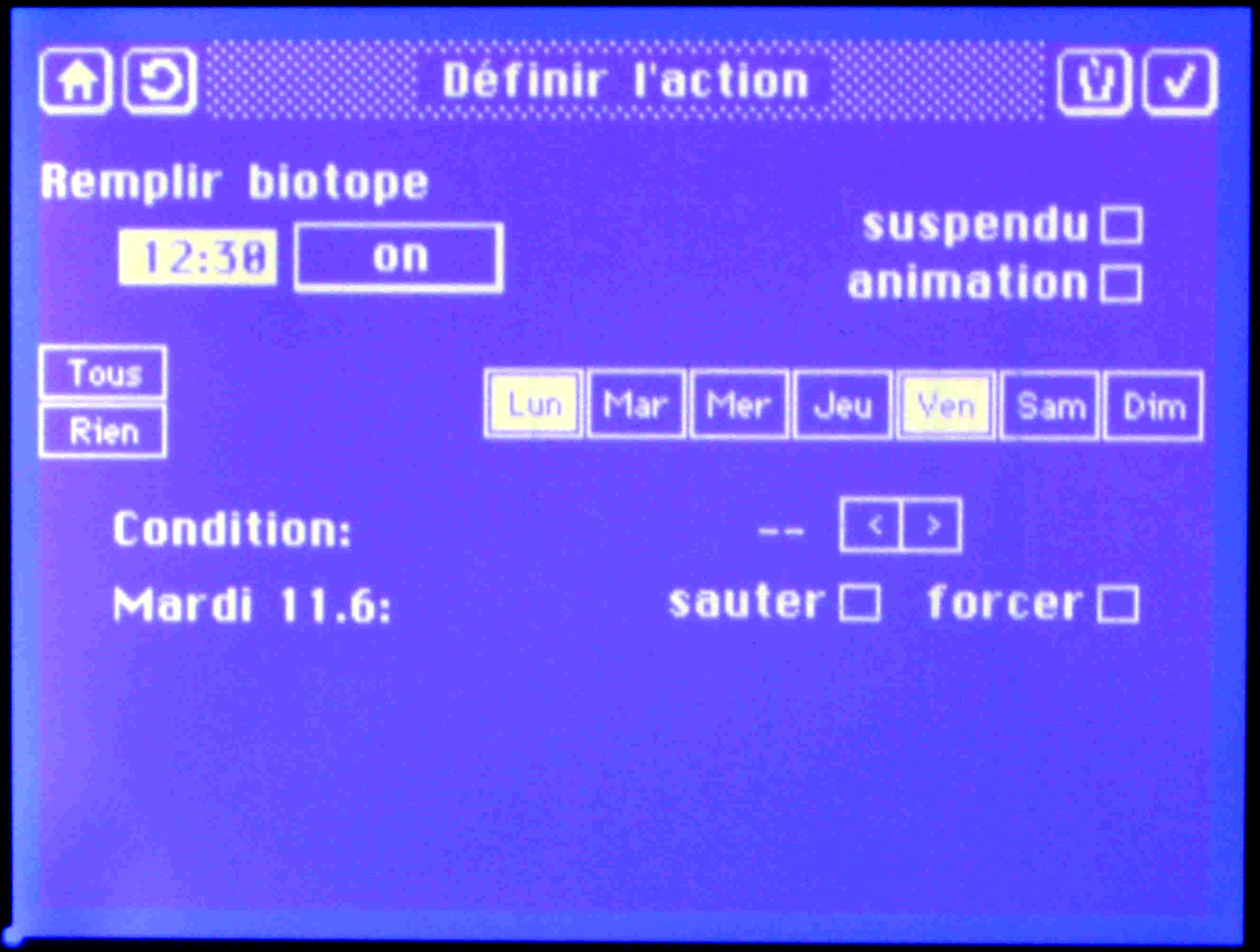
- editing events (creating and deleting events, defining their parameters, and controlling the time when events are scheduled),
- the display of the state of the system;
Additional types can be added any time - for instance, the development of a wall-clock with alarm functions has just been completed. For the time being, it is handled as an additional type, but possibly it should become a variant of a display-node.
Distinguishing between types of nodes is an issue of software
engineering: it facilitates the implementation of node software. All
nodes of a given type use the same software, differences between
different kinds of - say - target-nodes are handled under control of
Unix-style "environment variables" that conditionally
include code that takes care of the particular features to be
implemented.
2.1.2 Communication between Nodes
- the syntax and semantics of the protocol is the only element the nodes have in common;
- a modification of the protocol requires only those nodes to be re-compiled that handle message types whose representation has been modified;
- messages are broadcast over the network: nodes listen to bus traffic, each node only picks up the messages it considers significant for the tasks it assumes.
- following a button-hit on some node (a button- or display-node) triggers the action by sending a "device state change request" message to the master node;
- the master-node - it maintains a list of devices and their states
- updates its image of the the device
concerned;
- it then broadcasts an "action
request" message for effectively
modifying
the corresponding device; as an alternative, (2) and (3) can also be
directly generated by the master-node when the scheduler triggers an
event;
- the target-node which controls the device recognizes the request and modifies the state of the device;
- simultaneously, button- and display-nodes - they maintain shadow-information on the state of all (display-nodes) or of selected (button-nodes) devices - watch for action requests and - where appropriate - adapt their display correspondingly.
Complemented by simple dialogues that are run when the master-node or a target-node come up, this is all that is needed to keep a multi-node system in a consistent state; this approach even allows to re-boot any single node without loss of configuration data. This example also illustrates the fact that the careful definition of the protocol is a key item in the design of the system.
There is an additional important element that influences overall system design: the system is designed to be independent of interactions with a running PC.
2.2 CAN-Bus Deployment
2.2.1 Bus Characteristics
The bus uses category-5 cables that had been installed as spares at the time my local area Ethernet had been installed. The central and most important part of the network uses standard galvanically coupled differential CAN technology (MCP2551-like interface ICs, ISO 11898-2). The branch of the network that goes through the garden is implemented as an independent CAN bus: this "secondary bus" also uses ISO 11898-2 interface, but is connected to the central part by a bus-to-bus coupler node that uses optocouplers for galvanic separation. This concept has made its proof: it survived a direct hit in a thunderstorm that killed my TV and Hifi equipment.
Although the linear topology imposed by CAN suits large parts of the application topology, it has been necessary in some segments to recur to a token-ring like bus-over-star wiring.
Presently, the bus has an overall length of nearly 100 meters and supports a permanently growing number of nodes (more than a dozen at present). The bus is operated at a clock rate of 100 kBps: this is sufficiently fast to provide good real-time response and communication capacity, and is sufficiently slow to be safe with respect to problems of impedance matching and of stub-wiring lengths.
2.2.2 Target-Nodes
Target-nodes realize the interface to the physical devices. As an alternative to integrate the node and the device into a single equipment, nodes can be conceived as sub-centers - hubs at the origin of traditional wiring to the physical devices. In this case, a node controls several physical devices.
Example of a Target-Node
Figure 2.2.2-1 shows some devices that are controlled by the "garden" target-node,
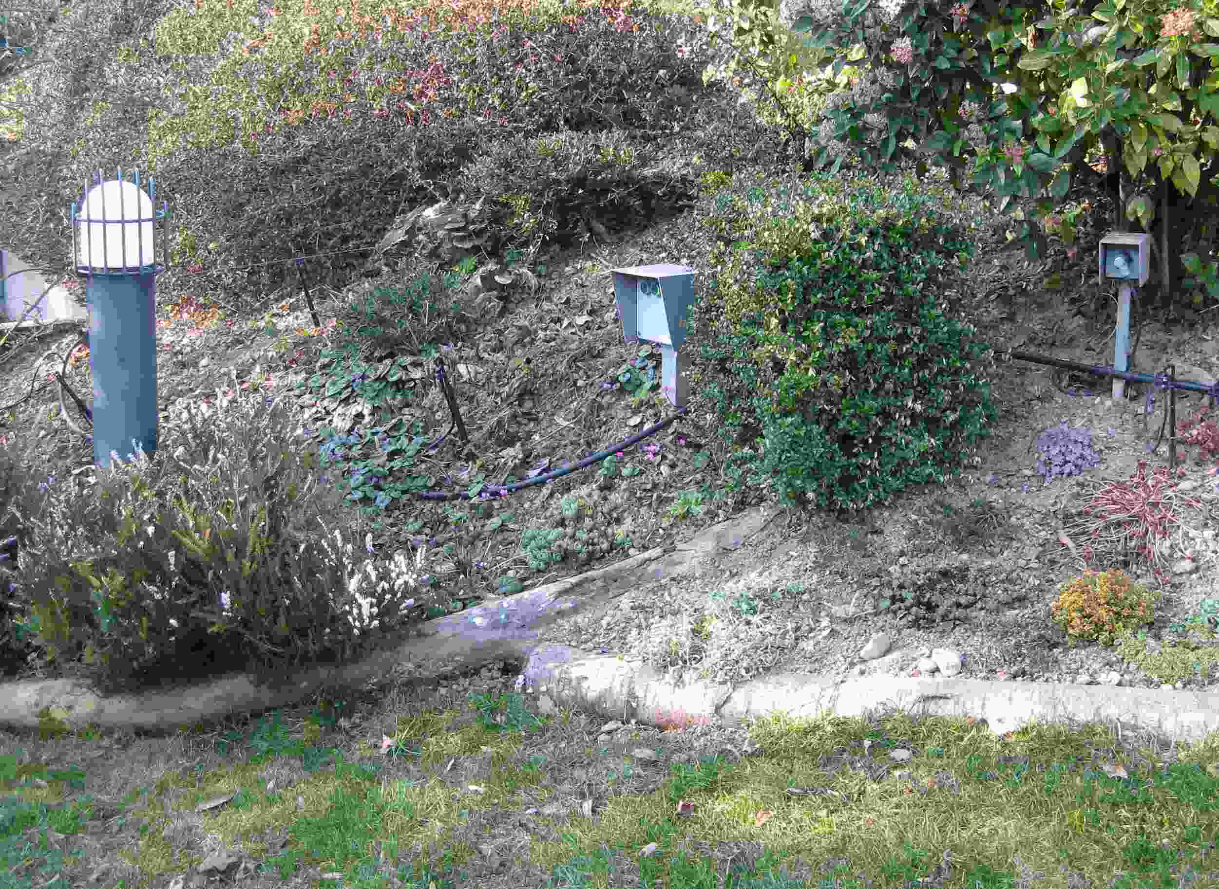
Figure 2.2.2-1: Device attached to the "garden" target-node
and Figure 2.2.2-2 the interior of the corresponding wiring closet
(it
is placed in
a small garden shed nearby) that accommodates
the node and auxiliary hardware: the Canstation-pcb (see node-hardware)
is hidden behind the bundle of yellow wires (top-right); the
torus at the left-hand side is the transformer for alimenting the
solenoid of a valve for filling up the pond, the device in the
left-bottom corner the filter for the lamp shown in Figure 2.2.2-1 -
removed from the lamp to avoid the iron core to
suffer from rusting.
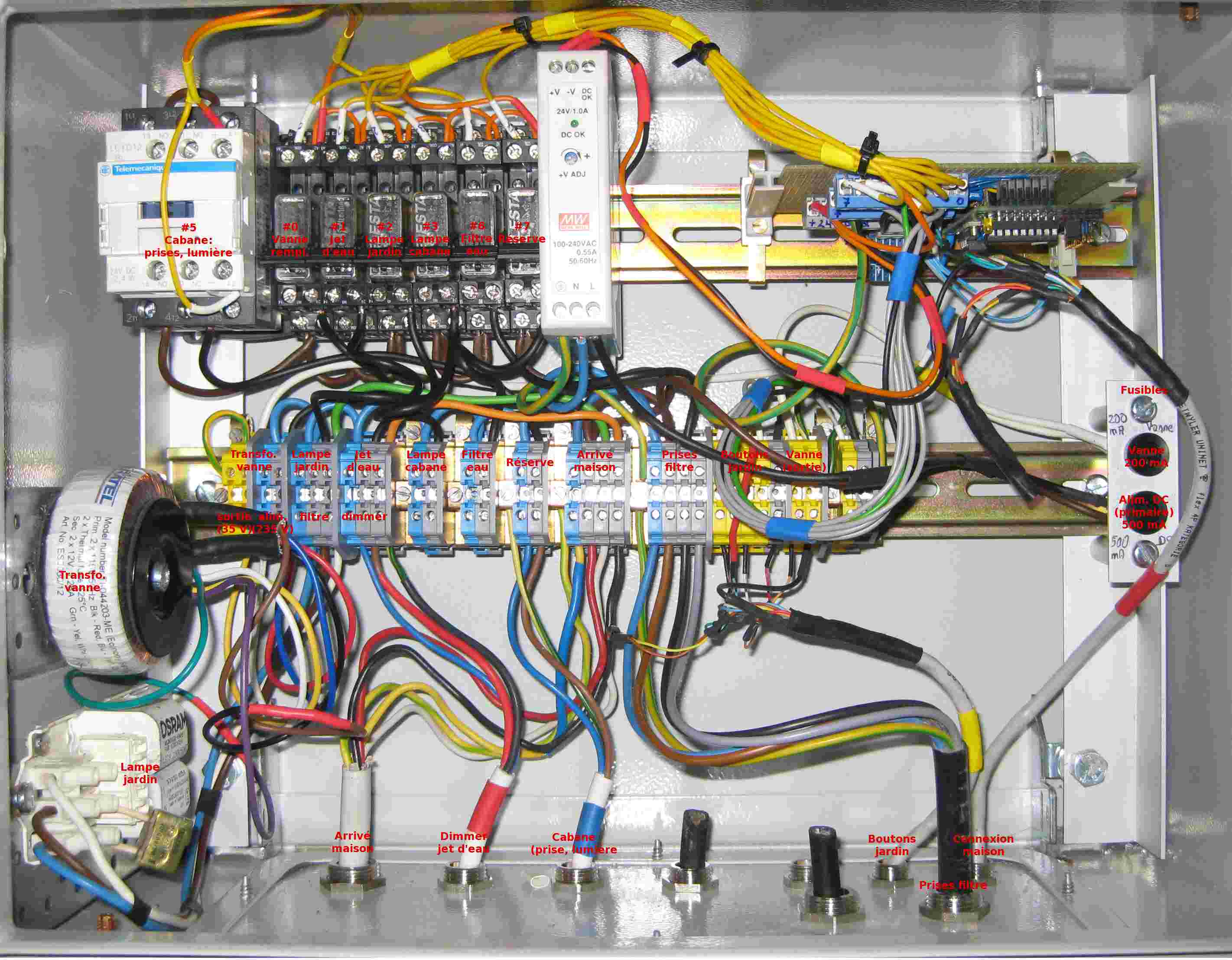
Figure 2.2.2-2: Wiring closet of the "garden" target-node
This example happens to illustrate the - by far - most complex of the nodes presently implemented. The average node consists of a small printed-circuit board (the "Canstation" board, see below) plus a couple of relays. Figure 2.2.2-3 shows another interesting example, a node that drives a set of 8 sprinkler circuits, realized as a pcb. Its main components are (1) a solid-state relay for each circuit, (2) a piggy-backed Canstation pcb - described in the next Section - and (3) a switched 5V DC power supply. The annular transformer that provides 24V AC for the sprinkler solenoids is not mounted on the pcb.

Figure 2.2.2-3: Sprinkler target-node
Powering Target-Nodes
2.3 Node Hardware
All nodes use AT90CAN128 AVR-processors (the smaller processors of that family are not easy to obtain, and given the low number of nodes the price is not an important issue; moreover, standardization on a single type of processor also has other advantages). Initially, prototype nodes had been successfully tested that use the Microchip MCP2515 controller - preference is given to the fully integrated AVR solution because it allows to make smaller printed-circuit boards and avoids the overhead for doing DMA between the processor and the controller; an MCP2515 controller is nevertheless used to obtain a second CAN interface in the bus-coupling target node that attaches the galvanically isolated secondary bus.
2.3.1 The Canstation Printed-Circuit Board
A small (45 by 55 mm) 2-layer printed-circuit board has been developed as a basic building block for all nodes; it is used
- either as stand-alone solution for implementing nodes (it can be equipped with an ULN2803 IC for driving loads of up to 500 mA) - its small dimensions make it fit into a standard 68 mm wall fitting,
- or in a piggy-back configuration (connectors on the Canstation board are arranged in a 0,1 inch grid which allows to plug the pcb onto a laboratory development board with a 0,1 inch grid),
- or as the support for building independent microprocessor-supported gadgets.
Figure 2.3.1-1 shows this Canstation printed-circuit board.
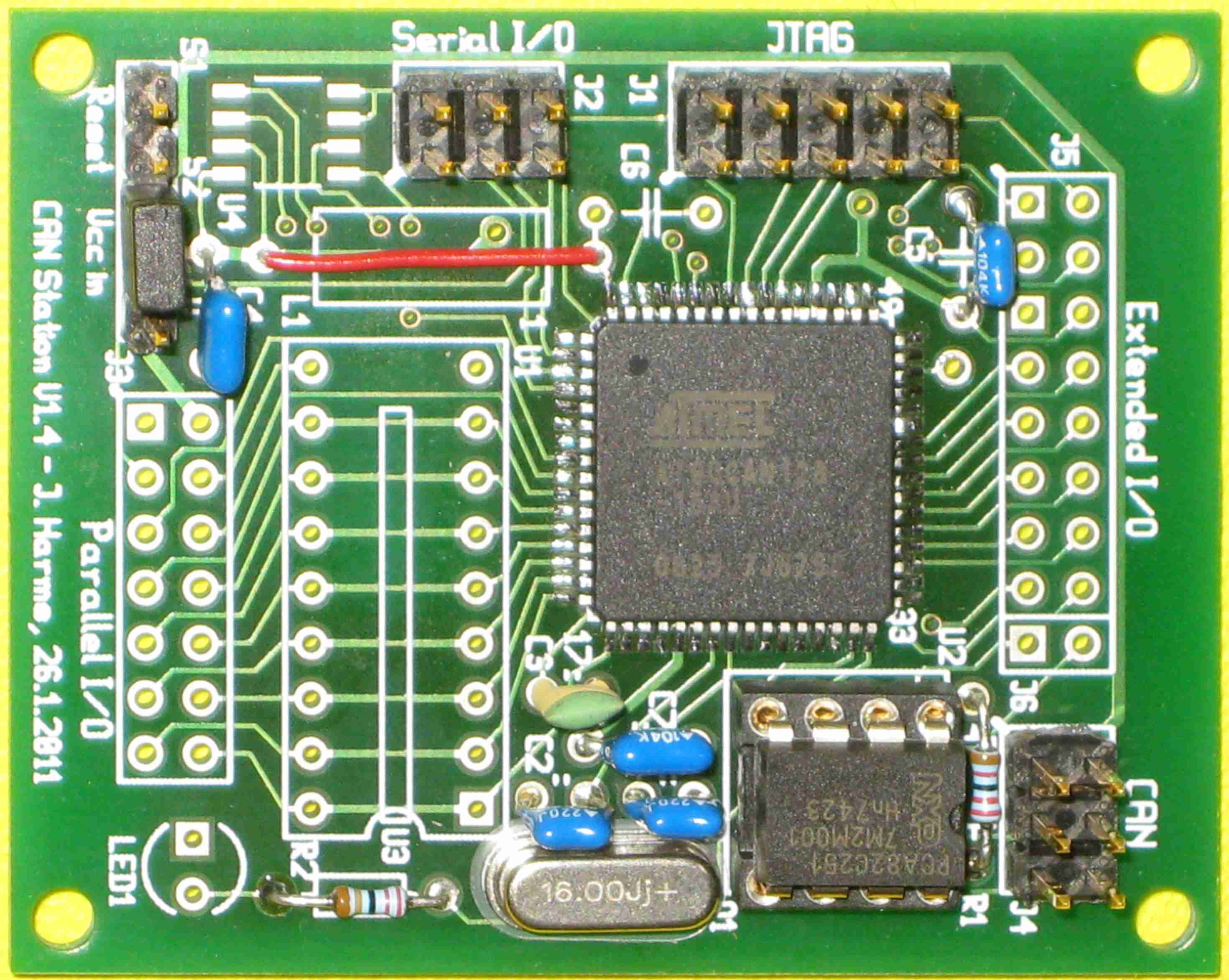
Figure 2.3.1-1: Canstation printed circuit board
The board uses a combination of SMD and of through-hole devices -
this is to facilitate stock keeping, but also because it is easier to
correct design errors on a board that had been conceived as a
prototype - an argument that is somewhat obsolete. The price I had
paid
for the last batch of 30 non-equipped boards was 228 Euros.
The board has connectors for
- wiring the board to the CAN-bus;
- wiring to the JTAG ICE;
- serial I/O (V.24);
- the main parallel I/O connector: ground, power, reset plus a set of parallel I/O ports:
- all bits of the processors B-register (also to be used for SPI
I/O),
- 2
bits of the E register;
- an extended I/O connector for nodes requiring to have access to additional ports:
- C-register,
- some ADC ports;
- a jumper controls whether the board is powered from the bus
connector or for the parallel I/O connector.
In the majority of nodes, only the main parallel I/O connector is used. If all B-register pins are used for output, the corresponding pcb leads can be cut under the "U3" socket (see figure 2.3.1-1) in favor of adding a ULN2803 (8 Darlington amplifiers that can drive loads of up to 500 mA).
2.3.2 Extended Canstation Board
At present, a slightly bigger (61 by 69 mm) pcb is being developed as an alternative which contains external RAM (a 32 kByte DS1244 non-volatile IC): although I have been surprised that - with careful design - the small size (4 kByte) of internal RAM never has been a severe restriction, experiments with stocking transient data (for instance for logging temperature charts) and with more sophistication for user programming of event sequences are easier to accomplish with "unlimited" availability of live memory. It is intended to use this extended Canstation for replacing the current master-node.
2.3.3 Additional Node Circuitry
Most nodes require the Canstation board to be complemented by additional circuitry that controls the physical device. The small number of nodes in general does not justify the development of node-specific printed circuits. Most nodes are therefore realized by manually wiring-up laboratory cards. So far there are two exceptions where the wiring effort, or the complexity of the wiring made me opt for implementing application-specific printed circuit boards:
- a printed-circuit board for controlling sets of 8 garden irrigation circuits (essentially a solid-state relay interface to 24V AC solenoids) (shown in Figure 2.2.2-3),
- a button array, with support for up to 10 buttons with LED indicators (as illustrated in Figure 2.1.1-1).
2.3.4 Use of Eeprom
Eeprom is configured not to be modified when new code is downloaded (the eeprom protection fuse bit is set). The lowest positions of eeprom contain in all nodes:
- a short string that identifies each individual CPU - defined when a board is cold-started,
- a bit-list that determines operating conditions (for instance, the printing of debugging output to the UART) - this can be modified with Avrdude,
- a 16-bit value that controls a "correction polynomial" (this is a parameter for the algorithm that adjusts the crystal-generated clock rate of each individual Canstation pcb to provide precisely a 10 msec software clock rate).
In the master node, eeprom is also used for storing the current list of events and the event parameters. This data is potentially subject to frequent modifications (intervention at the display-node): to prevent premature deterioration of eeprom, a mechanism is used that "ages" the most recently modified value in ram storage before it is copied to eeprom.
2.4 Node Software
2.4.1 Access to Common Resources
Conceptually, the activity of a node
corresponds to the execution of
several concurrent processes -
such as the reception of messages
over the network, the transmission of messages, the output of text to a
display panel, etc.
In fulfilling their tasks, these processes must
access critical resources -
resources that may only be used by only process at
a time - for instance the output channel to the CAN bus, access to the
display
panel, etc. Processes requiring access to critical resources must be
executed in mutual exclusion.
A small real-time operating system
(described in the next Section) is
used for supporting the implementation of processes. This operating
system handles the
synchronization of processes, but the decision was made to refrain from
handling mutual exclusion with mutex-like
constructs, the normally used approach: this would require to implement
process-queuing,
something that is problematic where live memory is very scarce.
Protecting Critical Resources
For the critical resource "UART" a different solution is implemented. The UART is only used for debugging, creating a separate process that owns the UART and handles I/O for other processes would be an overkill. The sharing of the UART is therefore achieved by a simple locking mechanism that uses active waiting: the library procedure for access to the UART uses the UDRIE bit of the UCSRB register as a locking bit. When output is launched, this bit is checked and set if it had been free - otherwise the calling process will loop on this check until the UART interrupt handler has cleared the bit at the end of the current output action. Active waiting is banned everywhere else since it deteriorates real-time response.
Example: Processes of the Display-Node
The display node is a good example to illustrate all this: if (1)
reading messages from the bus and, for instance, updating the display
of the clock, and (2) updating the display of button states in reaction
to user-generated events would be done without careful coordination,
the display would become messed up (note that the output to the
display-panel is interrupt-driven since the panel is a slow device).
The display-node is therefore organized to execute 3 processes:
- filters out the messages that must be handled by the display-node,
- sorts the messages according to their type,
- and than executes the code that needs to be run in consequence
(relagating output to the display panel to the panel process).
The "PanelProcess" handles
I/O to
the display panel; when the process wakes up, a parameter specifies
what
action needs to be done - for instance:
- launch a new "panel" (display of panel-specific information and buttons),
- when necessary, update the display of the real-time clock information or the temperature,
- when necessary, update the display of a device that has changed state,
- handle touch-screen events,
- launch an operator-requested node reset,
- etc.
The "SignalProcess" handles software-generated events:
- it is periodically activated by the real-time clock handler, it does - for instance
- the real-time clock-rate correction as specified in the correction polynomial for the specific node hardware,
- flashes the on-board LED to signal correct operation of the node;
- could also be activated to handle other software-generated events
- this is not needed for the display-node.
Therefore, if the CanRead process wants to write to the display, it must wake up the PanelProcess. It does this by calling "ProcessWait" (see below) with the calling argument specifying the text to be written.
Process definition for other types of nodes is very similar - for instance, all nodes have a CanRead and a SignalProcess.
2.4.2 Real-time
OS, Process Implementation
Several small operating systems for this kind of application do
already exist as open software. However - given the extremely simple
but
application-specific
nature of requirements described in the preceding paragraphs - a
substantially simpler OS has been developed for the support of process
concurrency in
the nodes of this system.
The development of this OS only required a minor effort, two rather small modules have been implemented:
- the "Kernel.c" module,
1400-lines
of C procedures (about one third of the lines are comments); the
procedures of this module assume all the effective work to be achieved
by the OS,
- plus a 400-line module with assembly-language procedures (again with a substantial amount of comment-lines) that implement the interface between the processes and the kernel - essentially, service-routines for context switching - the "Processes.c" module (the name has a .c suffix since the module is implemented as inline C-code).
The Kernel; Code of Processes
Processes are implemented as ordinary C procedures that execute
do-forever loops. The code of these procedures is activated
whenever
the corresponding process has something to do, the process relinquishes
control once that is finished. Activating and relinquishing is
performed by
the "kernel" - the code implemented by Kernel.c and Processes.c.
Kernel.c contains the procedure "main.c" that is launched after a node has been bootstrapped. During an initial phase, main.c calls initialization procedures - for peripheral libraries (i.e. CanInit, UartInit etc.), and also for initializing the software that implements the node: each node must have
- a procedure "InitModule" for setting up registers and global variables of the node,
- and a procedure "InitProcesses" for creating and launching the
processes of the node (which,
in turn is achieved for each process by calling the procedure
"ProcessInit" - see below).
Having the kernel call procedures in the application software is not very elegant, but there is no easy alternative. After this initialization phase, the approach is conceptually clean: the kernel executes an idle loop - de facto this is an "idle process" that simply waits for the interrupt handling to signal actions to be done:
- interrupt-handling does not directly interact with application processes,
- interrupts act on synchronization variables that are
permanently monitored by the idle loop,
- if the need to perform an action is thus detected, the kernel reacts by activating the corresponding process,
- after having done the necessary action, the process re-activates the idle-loop by calling one of the synchronization procedures of the module Processes.c (see below).
To minimize the requirements for live memory and to make the requirement for live memory predictable
- the operating system is non-pre-emptive and lets processes run to completion (i.e. until the process itself decides that it wants to be suspended),
- switching
of process-context is implemented by stack switching (adjusting the
hardware stack-pointer to point to the zone of memory that contains the
stack of the process to be executed),
- the number of processes implementing a node is kept as small as possible.
Since programming uses plain C, the constraints implied by the concepts described here (for instance the restriction to access resources as private to a given process) cannot be imposed - they must be observed as "programming discipline"; experience has shown that this is easy to observe and does not present a problem.
Service procedures
As already indicated, the procedures that implement the processes do not directly call any Kernel functions except the synchronization procedures implemented in the module Processor.c . A short enumeration of these procedures provides a good illustration of the co-operation between the OS (the "kernel") and the code of the processes that implement the nodes:
- "ProcessInit"
is called during the initialization of the
nodes. It reserves the stack for the process and defines its initial
content (process status is set to "ready-for-execution").
-
"ProcessResume" is called to re-activate a target-process after another process has relinquished the processing unit. It is only called by the kernel:
- the current stack-pointer of the idle loop is saved ,
- the stack-pointer saved when the target-process had been suspended is then restored,
- the status of the target process is set to "ready-for-execution".
-
"ProcessWait" is called by a process when it decides to suspend running and wait, typically for some action - like sending a message over the network or writing text to a display panel - to be completed (a parameter to the call indicates the condition for the wait):
- the current stack-pointer is saved in the context of the process,
- the status of the process is set to "process is waiting",
- the parameter of the call (wait condition) is saved in the
process context (for instance or a timed wait: the number of 10 msec
ticks to wait),
- finally the stack-pointer of the idle loop (the kernel) is restored to that saved in its context.
-
"ProcessSync" is used the for synchronising processes: it makes the calling process wait until a target process (specified as the argument of the call) becomes idle. The number of processes allowed to wait for synchronization by calling this procedure is limited to a single process - an easy way to prevent wait-deadlocks (an error is signaled if this condition is violated).
-
"StackSampling" is an auxiliary procedure for software development: when it is called, it stores the current size of the stack of a process. This allows to verify that the stack allocated to a process (determined when the process had been launched by the procedure "ProcessInit") contains enough spare memory. Although a rough estimation of the required size is possible (number and size of local variables, depth of procedure calls), there remains much guessing and it is good policy to verify the effectively used size. I have been surprised that presently I still have more than 1K bytes of spare memory in the display- and the master-nodes (much more in the target and button nodes).
2.4.3 Software for
Peripherals
(CAN, UART, DS18B20, DCF Receiver)
Practically all software available at the time when the project had
been
started did not support interrupts and
therefore needed re-writing (bear in mind that
this dates to many years back, and that
in the meantime new software will have been published).
CAN library
The CAN library for the AT90CAN processor provides the following procedures:
- CanInit (initialization of registers and variables)
- CANINIT_vect (interrupt service procedure)
- CanGetFrame (retrieve a received frame)
- CanSendFrame (launch the transmission of a frame)
- CanCheckWait (periodically called to check for excessive waiting time of frames pending transmission)
- CanKillFrame (kill a frame that waits for transmission)
- CanNormalId (auxiliary procedure: convert binary filter addresses)
- CanExtendedId (same for frames with an extended header)
This library is published at http://www.mikrocontroller.net/articles/CAN_Bibiliothek_f%C3%BCr_AT90CAN_Prozessoren.
At the beginning of the re-write, the logic to be implemented was studied by reading procedures written for the MCP2515 Microchip controller - some parts of my code reflect the logic implemented in http://www.kreatives-chaos.com/artikel/ansteuerung-eines-mcp2515 (Fabian Greif). The target-node that implements the coupling of the garden segment uses an MCP2515 for the additional CAN interface, its software is a re-write of these procedures, but with support for interrupt handling added.
UART support
Service procedures are
- UartInit (initialization of registers and variables)
- UART0_UDRE_vect (interrupt service procedure)
- PrintChar (print a single character)
- PrintString (print a 0-terminated string from ram memory)
- PrintString_P (print a 0-terminated string from flash memory)
These procedures have support for the locking mechanism described in the preceding Section. With respect to the corresponding procedures in the avr-libc library, they have the drawback that they cannot be used like standard Unix I/O, the C-"format" construct cannot be used. A couple of utility procedures for printing decimal and hexadecimal values have therefore also been created.
Support for DS18B20 temperature sensors
The original code is at http://www.mikrocontroller.net/topic/14792 (P. Dannegger). Here, a total re-write has not been necessary, but a lot of lavish extras have been eliminated and the software has been focused on having access to some few individual sensors.
The principal issue that caused some headache was the 1-wire software. The Dannegger code implements the timing issues by programming active waits; some of these periods are too short for efficiently handling them with an interrupt driven approach. But, as already mentioned, active waits are banned in this system in order to assure good real-time response.
The implementation of DS18B20 support is therefore based on a
small cheat: the
software does active waits, but it runs on a separate processor; this
processor is not directly connected to the bus and has no other
time-critical activities; it uses SPI to transfer
the measured data
to the master-node; for the master node, that corresponds to having a
variable with the current temperatures that is "automagically" updated.
DCF Receiver
The master-node uses a DCF antenna and -receiver for maintaining its time-of-the-day record. An algorithm has been implemented that analyses the pulse-width modulated output of this receiver and, as a result, maintains this data. The documentation available for the representation of the time broadcast from the DCF transmitter allowed without problems to implement that algorithm (see http://en.wikipedia.org/wiki/DCF77).
At present, this algorithm needs an entire 1-minute period to be received without any error for composing a timer-value. If the reception is bad (for instance during thunderstorm activity in the area), there may be periods of up to several hours without any perfect reception: the algorithm should be improved by adding a feature that combines fragments of correctly received data from disjoint 1-minute periods.2.5 Configuration Control
The configuration of the system is declared and stored in the form of data structures in C-procedures (i.e. Config.c and Events.c). Two kinds of configuration data are handled in a slightly different way:
- static configuration data does not change during system
life, it is compiled into flash memory and can be directly referenced
from
node software; into this category belong
- the description of all devices known to the system,
- their identifiers,
- textual names of the devices and device bits,
- static parameters;
- dynamic configuration data - the list of events - is represented as a list of records that can be modified while the system is running, it is maintained in eeprom memory; the procedures Config.c and Event.c compile an initial template of this list to flash memory; the template is copied to eeprom when a cold-start of the master node is performed; as long as the structure of the records is not modified, no re-compilation will be necessary when dynamic configuration data is modified;
Static configuration data is only mapped into the code of the master-node and of the display-node, the template of dynamic configuration data only into the master node. Therefore, only these nodes need to be re-built if corresponding configuration data is changed.
In terms of C-programming this is a very straightforward approach. In practice - since various items of configuration data structures refer to each other - this is somewhat complicated and requires careful handling. I would have liked to generate procedures like Config.c and Events.c with the help of some high-level language tool (probably using html or gtk), but - so far - there have always been more important issues that required immediate attention.
At present, this house bus system is used in two different sites with different configurations - moreover one in the French-speaking part of Switzerland, one in Austria, requiring the GUI to use either French or German. The software architecture selected for implementing the system is perfectly adequate to this situation.
2.6 Tools
for Development, Software Engineering
2.6.1 Choice of
Implementation Technology
The original bit-banger application was based on assembly-programmed Motorola 68HC11 processors. Deciding on the technology to deploy for the new implementation was not evident. Googling very rapidly made me aware of the attractiveness of AVR processors, but by accident and naively I did some exploratory work using the Conrad C-control product - which turned out a complete failure; on the positive side, this adventure has been a lesson that good library support and a lively exchange in community discussions are essential for choosing a platform.
Before that
background - and after a lot of more exploration, I re-discovered the
processors
of the AVR family and
decided to use CAN
technology (and, implicitly, a bus structure) and to base programming
on the C-language. The decision to go for
the avr-libc approach rather than to use Arduino was - to a large
degree - a question of personal taste; maybe the Conrad adventure also
had made me overly suspicious when I judged Arduino as excessively
"demo-oriented" in comparison to the "professional" aspects of avr-libc.
2.6.2 Software Development
Software is written in C (except the in-line assembler procedures for context-switching between processes).
Development uses a Linux environment: a gcc AVR cross-compiler, Unix "make" and the avr-libc library - see http://www.nongnu.org/avr-libc. Host communication for downloading and debugging uses an AVR JTAG ICE device and the avrdude utility program - http://savannah.nongnu.org/projects/avrdude.
Avrdude is a command-line tool: to make it easier and more efficient to use, a fronted GUI has been developed - a major asset when debugging implies concurrently running and controlling several nodes. The following Figures provide a short illustration of the properties of this tool (unpublished, but available on demand).
Figure 2.6.2-1: The Avrgui fronted (transfer-control)
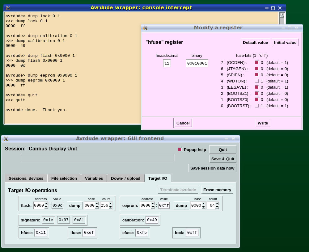
Figure 2.6.2-2: The Avrgui fronted (target processor control)
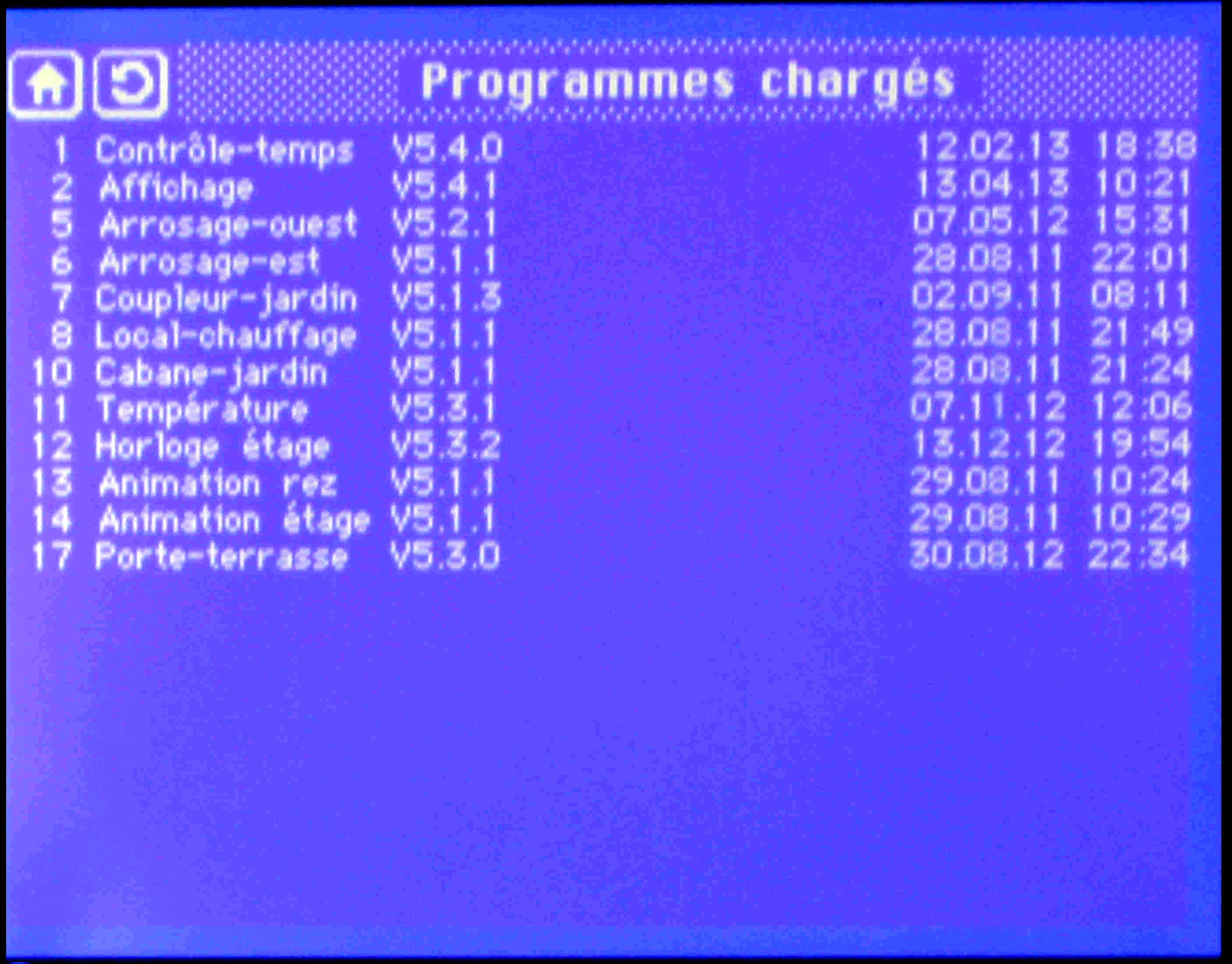
Presently the system does not have a feature for downloading and
bootstrapping new software over the bus: for most nodes an update is
very rarely necessary (as can be seen in Figure 4.2-4) - introducing a
bootstrap loader has been left as a low-priority issue for future
extensions.
2.6.3 Managing Source Code
The set of nodes that co-operate on the bus constitute a distributed system: although each node executes a perfectly autonomous program, these programs must be built and organized in a coherent fashion.
Node-Specific and Shared Directories
- one directory each per type of node (master, target ... ),
- one directory with procedures that are "shared" - are used by
more
than one or by all nodes (for instance the Kernel procedure, the
procedures of the CAN library etc),
- one directory for each configuration to be supported.
Directories with Node-Specific Code
- the source-code of all procedures created only for this type of node,
- links to the source-code of shared procedures used by the node,
- links to the procedures that contain configuration-specific data,
- the Makefile for building the object-code of the node.
Compilation and linking is achieved by the Unix "make" tool, with all instructions for "make" arranged into a Makefile. "Make" allows to use the Unix facility of environment variables - variables that are defined outside of "make" but that are accessible to "make" as parameters and for the control of conditional instructions. The Makefiles for nodes use such variables to differentiate between different flavors of a given node (for instance to select between different procedures for doing device I/O), and to determine the CAN message-identifier to which the node will respond; this allows to handle target-nodes and button-nodes as families of nodes with different properties.
These environment variables and the links to configuration-specific procedures can be manually defined by command-line operations. If the Avrgui fronted is used, the GUI takes care of the necessary actions.
This way of arranging the source code for the nodes on the bus has turned out as an extremely efficient way of managing the code of such a system, it can be strongly recommended for this kind of project.
Overall Volume of Code Developed
| Directory containing: |
Size: | |
|
(kBytes)
|
(lines)
|
|
| Shared procedures |
250
|
4990
|
| Configuration-specific procedures |
150
|
750
|
| Node-specific procedures (master) |
330
|
4470
|
| Node-specific procedures (display) |
440
|
7780
|
| Node-specific procedures
(target) |
100
|
2180
|
| Node-specific procedures (buttons) |
60
|
1280
|
2.6.4 Hardware Development
All printed circuit layouts and most schematics developed for this project are available as documents developed with the Leda family of tools - http://www.gpleda.org; some drawings are powerpoint-style documents produced with LibreOffice.